By Texas Instruments 269
Ⅰ.Introduction to LM2576
The LM2576 is a linear voltage regulator integrated circuit commonly used to step down a high voltage to a stable lower voltage. It was developed and produced by National Semiconductor (now part of Texas Instruments), so it is often called the LM2576.
The LM2576 series is a 3A current output step-down switching integrated voltage regulator circuit produced by National Semiconductor. It contains a fixed frequency oscillator (52kHz) and a reference regulator (1.23V), and has a complete protection circuit, including current Limiting and thermal shutdown circuits, etc., this device can be used to form an efficient voltage stabilizing circuit with only a few peripheral components.
Ⅱ.Introduction to LM2596
The LM2596 is a common switching regulator integrated circuit usually used to convert high voltage to a lower stable voltage.
The LM2596 series is a 3A current output step-down switching integrated voltage regulator chip produced by Texas Instruments (TI). It contains a fixed frequency oscillator (150KHZ) and a reference voltage regulator (1.23v), and has a complete protection circuit and current limits, thermal shutdown circuits, etc.
LM2596 is a switching voltage regulator of a step-down power management monolithic integrated circuit. It can output a drive current of 3A and has good linearity and load regulation characteristics. Fixed output versions include 3.3V, 5V, and 12V, and the adjustable version can output various voltages less than 37V.
Ⅲ.Main features of LM2576 and LM2596
1.LM2576
•Maximum input voltage:45V
•Maximum output current:3A
•Vibration frequency:52kHz
•Control mode:PWM
•Operating temperature range:-40℃ ~+125℃
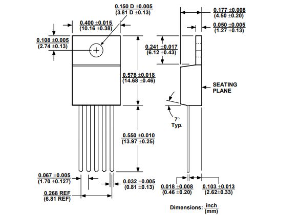
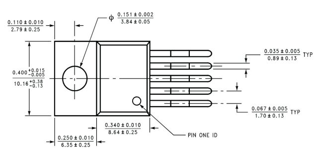
•Package form:TO-220 or TO-263
•Output voltage:3.3V, 5V, 12V, 15V and ADJ (adjustable) optional
•Conversion efficiency:75%~88% (efficiencies are different at different voltage outputs)
•Working mode control:TTL level compatible
•Working mode:low power consumption/normal mode can be controlled externally
•Device protection:thermal shutdown and current limit
•External components required:only four (non-adjustable) or six (adjustable)
2.LM2596
•Working mode control:TTL level compatible
•Device protection:thermal shutdown and current limit
•External components required:Four only (non-adjustable); six (adjustable)
•Working mode:low power consumption/normal two modes. Can be controlled externally
•Package form:5 pins (TO-220(T); TO-263(S)
•Output voltage:3.3V, 5V, 12V and (ADJ), etc., maximum output voltage 37V
Ⅳ.The working principle of LM2576 and LM2596
1.LM2576
•The LM2576 receives a high input voltage from the power supply, which typically needs to settle to a lower output voltage.
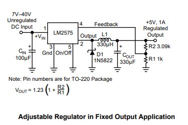
•In order to generate different output voltages, the negative terminal of the comparator is usually connected to the reference voltage (1.23V), and the positive terminal is connected to the voltage dividing resistor network. In this way, different resistance values can be selected according to the different output voltages, where R1=1kΩ( Open circuit when adjustable -ADJ), R2 are 1.7 kΩ (3.3V), 3.1 kΩ (5V), 8.84 kΩ (12V), 11.3 kΩ (15V) and 0 (-ADJ) respectively. The above resistors are already on the chip depending on the model. The interior has been precisely tuned.
•The LM2576 contains a built-in switching element, usually an internal transistor. This switching element switches at a certain frequency, usually at high speed, with very short on-off times.
•Compare the output of the output voltage divider resistor network with the internal reference voltage regulation value of 1.23V. If the voltage deviates, the amplifier can be used to control the output duty cycle of the internal oscillator to keep the output voltage stable.
•The LM2576 monitors the output voltage and adjusts the state of the switching elements through PWM control as necessary to maintain the required output voltage.
•LM2576 uses a PWM controller to change the switching time (pulse width) of the switching element at a certain frequency. By continuously adjusting the width of the pulse, the LM2576 can control the stability of the output voltage.
•By continuously adjusting the PWM control signal, the LM2576 keeps the output voltage at the desired stable level.
•The LM2576 also typically has protection features to prevent overload and overheating, protecting the circuit from damage.
2.LM2596
•Input voltage: LM2576 accepts high input voltage from the power supply. This can be a voltage from a battery, power adapter, or other source, which is usually higher than the desired output voltage.
•PWM control: LM2576 uses a PWM controller to precisely control the switching time of the switching elements. The PWM controller generates a pulse signal at a fixed frequency, and the width of the pulse (duty cycle) is adjusted according to changes in the output voltage.
•Switching element: The LM2576 contains an internal switching element, usually an internal switching transistor. This switching element switches on and off periodically to control the transfer of energy.
•Energy transfer: When the switching element is turned on, current flows through it to the output circuit. This transfers energy to the output circuit. When the switching element turns off, current stops flowing.
•Output capacitor: The output capacitor also needs to be connected to reduce the ripple of the output voltage and provide a stable output voltage.
•Output Inductor: An inductive component is usually connected in the output circuit to store electrical energy and smooth the output voltage. The inductor helps reduce fluctuations in the output voltage.
•Output voltage feedback: LM2576 monitors the output voltage by comparing the output voltage with a reference voltage. If the output voltage increases or decreases, the control circuit will adjust the duty cycle of the PWM signal accordingly to stabilize the output voltage.
Ⅴ.Typical applications of LM2576 and LM2596
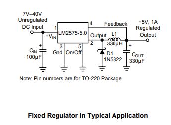
•LM2576
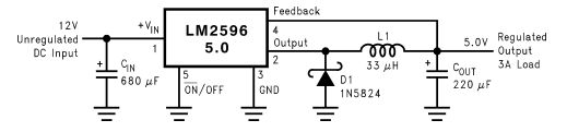
•LM2596
Ⅵ. Pin configuration of LM2576 and LM2596
1.LM2576
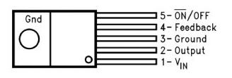
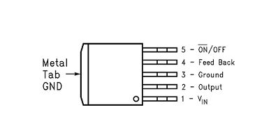
•Pin1(Vin): The voltage that needs to be adjusted can be provided as input to this Vin pin.
•Pin2(Output): This output pin is mainly used to control signal output.
•Pin3(GND): The GND pin is mainly connected to the GND pin of the circuit.
•Pin4(Feedback): This feedback input pin is mainly used to fix the 0/p voltage in case of variable output. To regulate the o/p voltage, it is related to the center of the feedback divider circuit. In the fixed output case, this pin is connected to the capacitor.
•Pin5(ON/OFF): The ON/OFF pin is the input enable pin, this pin is connected to GND to enable the voltage regulator. To disable the voltage regulator, connect this pin to logic high.
2.LM2596
•Pin1(Vin): is the input power pin, connected to the original power supply, usually DC power supply. The supply voltage range is 4.5V to 40V.
•Pin2 (GND): It is the ground pin of the LM2596 chip, connected to the negative pole of the power supply or ground.
•Pin3(Vout): The Vout pin is the output power pin of the LM2596 chip and is connected to the load. It provides the ability to adjust the output voltage. Vout can adjust the output voltage as needed, and the voltage adjustment is completed through external components.
•Pin4 (Feedback): The Feedback pin is the feedback pin of the LM2596 chip. It is connected to the resistor divider above the output voltage to control the output voltage. By changing the resistor voltage dividing ratio, different output voltage values can be achieved.
•Pin5 (ON/OFF): It is the switch control pin of the LM2596 chip. When open circuit, the chip is in the off state, and when short circuit, it is in the open state.
•Pin6(Vref): The Vref pin is the reference voltage output pin of the LM2596 chip. Normally, this pin is not needed.
•Pin7 (Error Amplifier Output): The Error Amplifier Output pin is the error amplifier output pin of the LM2596 chip. Normally, this pin is not needed.
Ⅶ.Packaging of LM2576 and LM2596
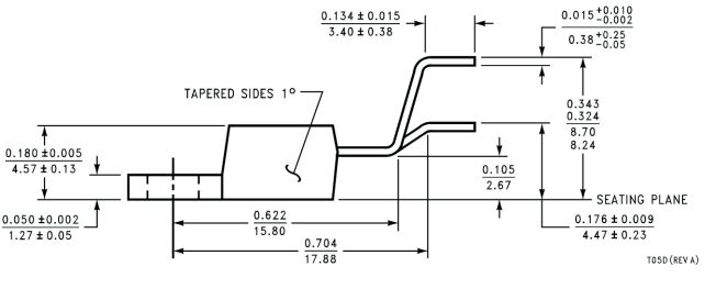
•LM2576
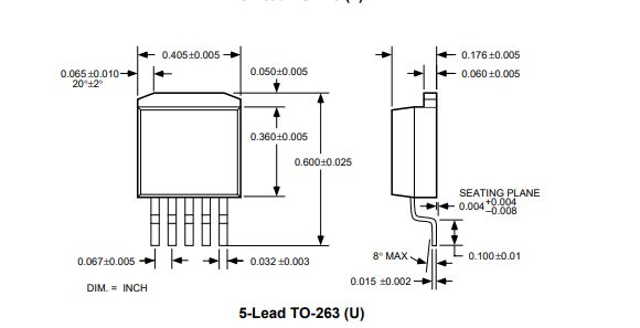
•LM2596
Frequently Asked Questions
1.What are the alternative models of LM2576?
LM2577, LM317, LM2596S, LT1083, MC34063, AP1501
2.What are the alternative models of LM2596?
LM2575, LM2597, LM2574, XL4015, MP2307
3.What are the advantages and limitations of LM2576 compared with other voltage regulator chips?
The LM2576 is capable of providing a stable output voltage that remains stable even when the input voltage fluctuates widely. This makes it suitable for applications requiring reliable power. A switching regulator can be more complex to design than a linear regulator because it requires external components such as inductors and capacitors to ensure proper operation.
4.What are the protection functions of LM2596?
Overload protection, current limit, short circuit protection, input voltage reverse polarity protection, overheating protection