By STMicroelectronics 1333
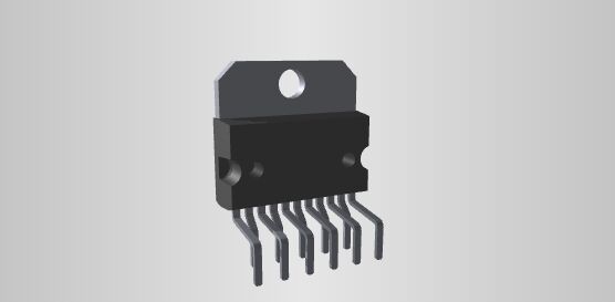
TDA2009A is an integrated audio power amplifier chip commonly used in audio amplification applications. This chip is a product produced by STMicroelectronics and is used to enhance the power of audio signals to drive speakers or sound systems.
The TDA2009A has a dual-channel design that can drive left and right channel speakers, making it suitable for stereo applications. It provides a certain output power and has some built-in protection functions, such as overheating protection and short-circuit protection, to ensure reliability and safety during operation.
Ⅰ.Specifications of TDA2009A
Products:Audio Amplifiers
Class:Class-AB
Output power:12.5 W
Installation style:Through Hole
Type:2-Channel Stereo
Package/Cabinet:Multiwatt-11
Audio-Load Impedance:8 Ohms
THD+noise:0.2%
Power supply voltage-Max:28V
Supply voltage-minimum:8V
Minimum operating temperature:-40℃
Maximum operating temperature:+150℃
Package:Tube
Description/Function:Speaker
Gain:36dB
Height:10.7 mm
Number of channels:2 Channel
Working power current:3.5 A
Working power supply voltage:9V, 12V, 15V, 18V, 24V
Output current:4.5 A
Pd-Power dissipation:20 W
PSRR-Power Supply Rejection Ratio:55 dB
Quiescent current:60.0 mA
Output current (Max):4500 mA
Dissipated power (Max):20000 mW
Ⅱ.Main functions of TDA2009A
1.Audio signal amplification: The main function of TDA2009A is to amplify low-level audio signals into higher-power audio signals so that they can drive speakers or drive sound systems. It boosts the volume of audio sources to make music or sounds clearer and louder.
2.Output power: The output power of TDA2009A is usually enough to drive front or rear sound field speakers. In a home audio system, it can also drive a pair of main speakers and a pair of surround speakers. However, for larger speakers or applications requiring higher output power, it may be necessary to use a more powerful amplifier or multiple amplifier chips to meet the demand.
3.Dual-channel design: TDA2009A is usually a dual-channel design, which can process the audio signals of the left channel and the right channel at the same time, and is suitable for stereo applications. This makes it ideal for audio systems that need to drive two speakers separately.
4.Protection function: The chip usually has built-in protection functions, such as overheating protection and short-circuit protection, to prevent damage to the chip due to overheating or circuit failure. This helps ensure system reliability and security.
5.TDA2009A is usually designed to provide relatively low distortion and noise levels to maintain the high quality of the audio signal. Distortion refers to the deformation or distortion of the audio signal during the amplification process, while noise refers to the unwanted distortion in the audio signal. background noise. Low distortion and low noise are key factors for high-quality audio, especially in high-fidelity sound systems. The TDA2009A uses advanced circuit design and manufacturing processes to provide relatively low distortion and noise levels, which makes it ideal for driving small to medium-sized speakers as it is able to clearly convey the audio signal and maintain audio quality. However, it is important to note that distortion and noise levels may still be affected by other factors, such as circuit design, power quality, external interference, etc.
Ⅲ.Pin layout of TDA2009A
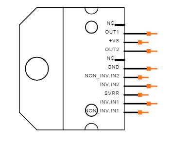
•Pin 1 (VS):Supply voltage pin, connect to the positive power supply.
•Pin 2 (GND):Ground pin, connected to the negative pole of the power supply.
•Pin 3 (INPUT-):Left channel input negative pole.
•Pin 4 (INPUT+):Left channel input positive.
•Pin 5 (SVR):Input resistor voltage divider pin. By connecting a resistor to ground, you set the amplifier's voltage gain.
•Pin 6 (OUTPUT1):Left channel output.
•Pin 7 (OUTPUT2):Right channel output.
•Pin 8 (INPUTR+):Right channel input positive.
•Pin 9 (INPUTR-):Right channel input negative pole.
•Pin 10 (SVR2):Another input resistor voltage divider pin used to set the voltage gain of another amplifier.
•Pin 11 (SVR1):Connect to supply voltage pin (VS) to provide additional supply voltage.
Ⅳ.Working principle of TDA2009A
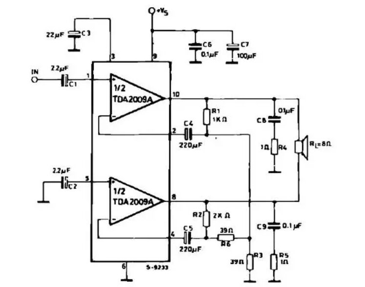
1.Input stage: The input audio signal enters the chip through pin 3 (INPUT-) and pin 4 (INPUT+). The two input signals are fed into the left and right channel amplifier circuits respectively.
2.Voltage gain adjustment: Pin 5 (SVR) and pin 11 (SVR2) are connected to the input impedance voltage divider network to adjust the voltage gain of the amplifier. This allows the magnification to be adjusted according to the needs of the application.
3.Differential Amplifier: The input signal passes through a differential amplifier where the voltage difference between pin 3 and pin 4 is amplified. This is to increase the amplitude of the input signal so that it can better drive the loudspeaker in the subsequent amplification stage.
4.Output stage: The amplified signal enters the output stage and drives the left and right channel speakers through pin 6 (OUTPUT1) and pin 7 (OUTPUT2) respectively. The output stage usually adopts a Class AB power amplifier design, which combines the characteristics of Class A and Class B power amplifiers to achieve a balance between power efficiency and distortion.
5.Protection circuit: TDA2009A usually contains overheating protection and short-circuit protection circuits to prevent the chip from being damaged due to overheating or load short circuit. These protection mechanisms help ensure system stability and reliability.
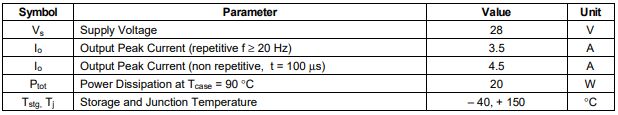
Ⅴ.Absolute Maximum Ratings of TDA2009A
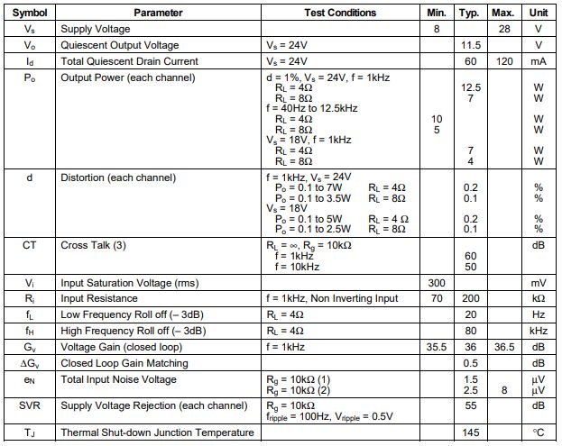
Ⅵ.Electrical Characteristics of TDA2009A
(refer to the stereo application circuit, Tamb = 25℃,Vs=24V,Gv=36dB, unless otherwise specified)
Ⅶ.Application fields of TDA2009A
1.Car audio system: TDA2009A is often used in car audio systems to amplify the audio signals in the car to provide enough power to drive the speakers in the car.
2.Multimedia speakers: TDA2009A is suitable for multimedia speakers, such as computer speakers or other digital audio playback devices.
3.Home audio system: This chip can be used in home audio systems, including stereo systems or multi-channel audio systems. It provides the audio power needed for home entertainment systems.
4.Wireless audio equipment: The TDA2009A can be used in wireless audio equipment, such as wireless speaker systems, enabling it to provide clear, powerful sound.
5.TV sound system: TDA2009A can be used in TV sound systems to enhance the built-in audio amplification function of the TV and provide a better sound experience.
Frequently Asked Questions
1.What are the key features of the TDA2009A?
The TDA2009A features dual-channel amplification, moderate output power, voltage gain adjustment, and built-in protection mechanisms like thermal and short-circuit protection.
2.What are the protection features in the TDA2009A?
The TDA2009A typically includes protection features such as thermal shutdown to prevent overheating and short-circuit protection to safeguard the amplifier in case of a load short.
3.How is the voltage gain adjusted in the TDA2009A?
The voltage gain in the TDA2009A can be adjusted by using external resistors connected to specific pins, such as SVR and SVR2.
4.What is the typical output power of the TDA2009A?
The TDA2009A typically provides a moderate output power suitable for driving speakers in audio applications. The actual output power depends on the specific operating conditions and the circuit configuration.