By Signetics Corporation 2148
Ⅰ.Introduction to NE555
NE555 is a classic integrated circuit and one of the commonly used devices in timer and PWM applications. The NE55 is an 8-pin time base integrated circuit, released by Signetics Corporation around 1971. At the time, it was the only very fast and commercial timer IC. NE555 is small in size, light in weight, stable and reliable, has a large operating power range, strong current supply capability at the output end, high timing accuracy, good temperature stability, and is cheap.
NE555 is a type of timer IC in the 555 series. The pins and usage methods of the 555 series ICs are compatible, but different models have different oscillation frequencies due to their stability, power saving, and so on. 555 is a widely used and versatile timing integrated circuit. It only requires a small amount of resistors and capacitors to generate pulse signals of various frequencies required by digital circuits.
Ⅱ.Introduction to TLC555
TLC555 supports two basic working modes: monostable and astable, similar to NE555.
TLC555 is an integrated circuit similar to NE555, a device for timer and pulse width modulation (PWM) applications. It is a derivative model launched by Texas Instruments (TI). It is basically the same in function as the NE555, but has been improved in some aspects.
The TLC555 is a monolithic timing circuit fabricated using the TI LinCMOS process. The timer is fully compatible with CMOS, TTL, and MOS logic, and operates at frequencies up to 2 MHz. Because of its high input impedance, this device uses smaller timing capacitors than those used by the NE555. As a result, more accurate time delays and oscillations are possible. Power consumption is low across the full range of power-supply voltage.
Ⅲ.Main features of NE555 and TLC555
•NE555
1.Working mode: NE555 has three basic working modes, including monostable, astable and comparator modes, making it suitable for a variety of applications.
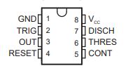
2.Pin structure: NE555 has 8 pins, including power pins, ground pins, output pins, etc. The pin structure is relatively simple and easy to use.
3.Power supply voltage range: NE555 can operate within a wide power supply voltage range, usually 4.5V to 15V, providing certain flexibility.
4.Adjustability: The timing cycle of NE555 can be adjusted through external resistors and capacitors to adapt it to different application needs.
5.Stability: NE555 has a stable reference voltage source inside, which can provide a relatively stable timing cycle.
6.Output driving capability: The output pin of NE555 can provide high current and is suitable for driving external loads.
7.Reliability: NE555 is a time-proven device that is widely adopted for its reliability and stability.
8.Widely used: NE555 is widely used in various electronic circuits such as timers, frequency dividers, pulse width modulators, pulse generators, etc.
9.Cost-effectiveness: NE555 is a relatively affordable integrated circuit with low cost and suitable for mass production.
10.Low power consumption version: Some variant models provide low power consumption version, suitable for applications where energy consumption needs to be considered.
•TLC555
1.Wide voltage range: TLC555 can operate within a wider supply voltage range, usually 2V to 15V, providing greater power flexibility.
2.Low power consumption: Compared with NE555, TLC555 has lower power consumption in some aspects, making it more suitable for applications with higher energy consumption requirements.
3.Pin compatibility: The pin functions of TLC555 are basically the same as those of NE555, so it can directly replace NE555 in some designs without modifying the circuit, providing a certain degree of compatibility.
4.High precision: TLC555 has better precision performance in some aspects, including lower temperature drift and lower input current, and is suitable for some applications that require higher stability and precision. ‘
5.Application fields: TLC555 is widely used in various electronic circuits such as timers, pulse width modulation, frequency division, pulse generators, etc.
Ⅳ.Main parameters of NE555 and TLC555
1.NE555
•Power supply voltage range: 4.5V-15V
•Operating temperature range: 0°C~70°C
•Output current capability: 5mA-200mA
•Current consumption: static current and dynamic current
•Power supply current: Describes the current consumed by the overall power supply of the device.
•Temperature drift: Describes how device performance changes with temperature.
•Threshold voltage: The voltage threshold that triggers monostable mode, i.e. the voltage at which the capacitor begins to charge.
•Output voltage range: The voltage range of the NE555's output pin in high and low states.
•Trigger voltage: The voltage threshold that triggers the bistable mode, that is, the voltage at which the capacitor starts charging and discharging.
•Input Current: Current requirements for input pins, including flip-flop and reset pins.
•Pin drive capability: Describes the drive capability of the NE555 output pin, that is, its ability to drive an external load.
•Duty cycle range: The ratio of the high level time of the wave to the period in bistable mode.
2.TLC555
•Power supply voltage range: 2V-15V
•Operating temperature range: -40°C~125°C
•Output voltage range: The voltage range of the output pin of TLC555 in high and low states.
•Input Current: Current requirements for input pins, including flip-flop and reset pins.
•Threshold voltage: The voltage threshold that triggers monostable mode.
•Power supply current: Describes the current consumed by the overall power supply of the device.
•Pin drive capability: Describes the drive capability of the TLC555 output pin.
•Duty cycle range: The ratio of the high level time of the wave to the period in bistable mode.
•Power supply rejection ratio: Describes the degree of output suppression when the power supply voltage decreases.
Ⅴ.Pin configuration of NE555 and TLC555
•NE555
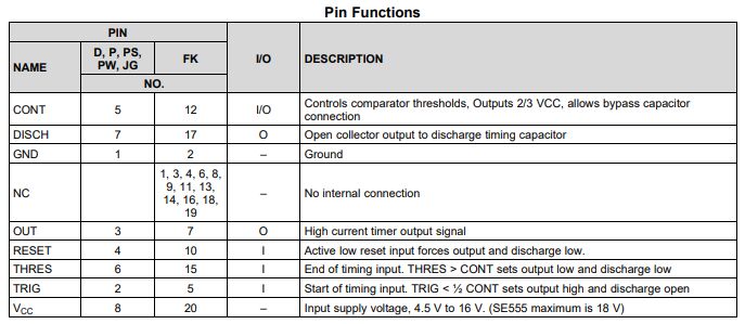
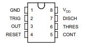
•TLC555

Ⅵ.Application of NE555 and TLC555
•NE555
1.Pulse generator: In clock circuits, pulse generators can be used to generate a timing signal to control operations in digital circuits. For example, the NE555 can be used to generate a pulse signal with an adjustable duty cycle, which can be used to synchronize circuit operations or serve as a clock signal for the CPU. In frequency modulation applications, the NE555 can be used to generate FM signals. By changing the voltage input to the NE555, you can change the frequency of the output. This method is often used in wireless communications, such as in FM radio.
2.Square wave generator: In bistable mode, NE555 can generate a stable square wave signal, suitable for circuits that require stable square wave output, such as driving stepper motors.
3.PWM: NE555 can generate adjustable pulse width modulation signals, which is suitable for motor control, light dimming and other applications that require pulse width modulation.
4.Single pulse generator: The monostable mode of NE555 can be used to generate a single pulse signal, suitable for applications such as control circuits and triggers.
5.Frequency divider: NE555 can be used as a frequency divider to divide the input frequency and output it, which is suitable for timing generation in digital circuits.
•TLC555
1.Timer: In timer applications, the TLC555 is usually configured as a monostable multivibrator. When a trigger signal is received, the TLC555 will jump from one steady state to another, and then return to the original steady state after a period of time. This time delay is determined by the RC network and therefore can be precisely controlled.
2.Electronic clock: By configuring TLC555 as a frequency divider, it can be used in digital clock circuits to generate clock signals of seconds, minutes, and hours.
3.Sound Effect Generator: The TLC555 can be used to generate sound effects such as pulse modulated audio.
4.Pulse counter: Combined with other logic devices, TLC555 can form a simple pulse counter for event counting.
5.Trigger: It has two trigger input pins, Trig-In and Echo-Out. When the Trig-ln pin receives a valid trigger signal, the TLC555 will jump from one steady state to the other. steady state, and then remains in this new steady state until a trigger signal is received again. By configuring the TLC555 as a bistable multivibrator, it can be used to design flip-flop circuits. For example, the Trig-ln pin can be connected to the controller's trigger circuit to trigger the TLC555's output signal when the controller detects a specific input signal.
Ⅶ.Electrical characteristics of NE555 and TLC555
•NE555
over operating free-air temperature range (unless otherwise noted)

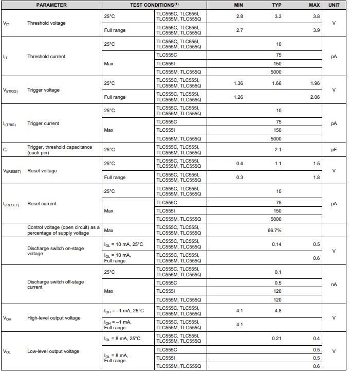
•TLC555
Vcc=5V to 15 V, TA=25°C (unless otherwise noted)
Ⅷ.The difference between NE555 and TLC555
1.Manufacturer:
•NE555 is a standard model produced by multiple manufacturers, including STMicroelectronics, Texas Instruments, Fairchild Semiconductor, etc.
•TLC555 is a variant model produced by Texas Instruments (TI), which is an improvement and optimization of NE555.
2.Low power consumption: Compared with NE555, TLC555 has lower power consumption in some aspects and is suitable for applications with high energy consumption requirements.
3.Power supply voltage range:
•NE555 typically operates within a supply voltage range of 4.5V to 15V.
•The TLC555 has a wider supply voltage range, typically 2V to 15V, providing greater power supply flexibility.
4.Accuracy and stability: TLC555 has better precision performance in some aspects, including lower temperature drift and lower input current, making it more suitable for applications that require higher stability and accuracy.
5.Pin compatibility: The pin functions of TLC555 are basically the same as those of NE555, but they are not completely compatible. In some circuits, TLC555 can be directly replaced by NE555, but in some special cases adaptation may be required.
6.Cost-effectiveness:
•NE555 is an affordable integrated circuit with a relatively low price.
•The TLC555 is also economical, but may be more competitive in some applications with special performance requirements.
Ⅸ.Common points between NE555 and TLC555
1.Basic working principle: NE555 and TLC555 are both timer and PWM integrated circuits, with basic working principles of monostable mode and astable mode.
2.Application scope: NE555 and TLC555 are widely used in similar fields, such as pulse generation, square wave generation, timers, PWM, etc. They are common basic devices in electronic circuit design.
3.Adjustability: Both NE555 and TLC555 have adjustable timing cycles, and the pulse frequency and width can be adjusted through external resistors and capacitors to meet different application needs.
4.Operating modes: Both support basic operating modes of monostable and bistable, allowing them to provide flexibility in a variety of applications.
Frequently Asked Questions
1.What are the common problems during use of NE555?
The external circuit connection is incorrect, the capacitor or resistance value is improperly selected, and the power supply voltage is unstable; the trigger pulse input is incorrect, the external component is faulty, and the power supply voltage is lower than the working requirements of the NE555; the external component is connected incorrectly, and the power supply voltage is unstable.
2.Under what circumstances might the supply voltage of the TLC555 affect its performance?
When the supply voltage of the TLC555 is lower than its specified minimum operating voltage, it may not work properly or the output may be unstable. Therefore, it is necessary to ensure that the power supply voltage is within the specified range, usually 2V to 15V. Changes in the supply voltage may cause instability in the TLC555 output level. Under extreme supply voltage conditions, the output level may not reach the specified high or low level.
3.How accurate is the NE555 timer?
For sub-1% accuracy, the NE555 timer is ideal. For better than 0.1% accuracy, consider digital or crystal technology. If the power supply voltage changes quickly relative to the timing period, the NE555 sometimes has output jitter problems.
4.What type of load can the output pin of TLC555 drive?
The output pins of the TLC555 can be used to drive CMOS and TTL logic gates because these gates generally have higher input impedance and require less load on the output. The TLC555 can be used to drive low-power LEDs, but attention needs to be paid to current limits and voltage requirements to ensure use within the specified parameters.