By Texas Instruments 1361
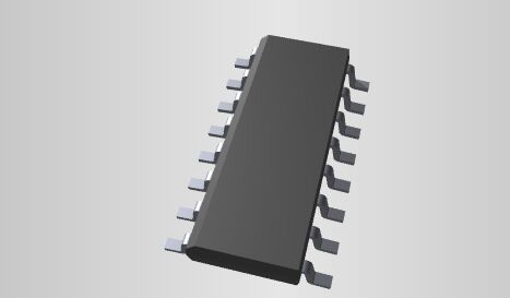
ULN2003 is an integrated circuit that is commonly used as a device to drive and amplify the output signals of microcontrollers to control high current loads. It is composed of multiple transistors (usually NPN transistors) and related circuits to provide current amplification and isolation functions.
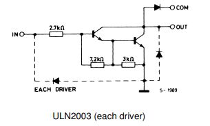
ULN2003 is a high-voltage, high-current composite transistor array, consisting of seven silicon NPN composite transistors. Each pair of Darlingtons is connected in series with a 2.7K base resistor. It can be used with TTL and CMOS circuits at an operating voltage of 5V. Direct connection allows direct processing of data that previously required standard logic buffers.
Ⅰ.The role of ULN2003
1.Current amplification: ULN2003 can convert the low current signal provided by the microcontroller or other control circuit into a high current signal, so that it can control the load requiring large current. This is useful for applications where the load requires larger currents to operate properly.
2.Drive loads: The main function of ULN2003 is to drive large current loads, such as motors, relays, light bulbs, stepper motors, etc. It can receive an input signal from a microcontroller or other low-current signal source and amplify it into a current high enough to control these loads.
3.Simplify circuit design: The use of ULN2003 can simplify circuit design, reduce the number of external components required, and reduce system costs. It allows engineers to control high current loads more easily without having to design complex current amplification circuits.
4.Isolation protection: ULN2003 also provides electrical isolation to protect microcontrollers or other control circuits from load voltage and current. This helps prevent potential electrical interference and damage.
5.Process data: JLN2003 is a high-voltage, high-current Darlington array, consisting of seven silicon NPN Darlington tubes. The characteristics of this circuit are as follows: Each pair of Darlingtons of ULN2003 is connected in series with a 2.7K base resistor. It can be directly connected to TTL and CMOS circuits at an operating voltage of 5V, and can directly handle the processing that originally required standard logic buffers. The data.
Ⅱ.Working principle of ULN2003
•The working principle of the ULN2003 stepper motor driver is to convert low-level input signals into high-level output signals so that the motor can work correctly. Its working principle is: when the input power is connected, the transistor converts the low-level signal into a high-level signal to control the rotation direction of the motor, thereby realizing the forward and reverse rotation of the motor; an inverter is used to convert the low-level input signal into a high-level signal. The signal is converted into a high-level output signal, and a resistor is used to reduce the output high-level signal; a capacitor is used to filter the high-level signal to obtain a smoother output signal, and ultimately control the rotation of the motor.
•When an input pin is activated, i.e. the input signal is set to a high level (usually logic 1), the transistor associated with that input pin conducts. This causes the current supplied from the common supply pin to flow through the conducting transistor and then to the corresponding load.
•The input of the ULN2003 accepts low current signals from a microcontroller or other control circuit. Each input pin corresponds to a transistor inside the ULN2003.
•ULN2003 also provides electrical isolation between the input and output through the configuration of the internal current amplifier, thereby protecting the microcontroller or other control circuitry from load voltage and current. This helps prevent potential electrical interference and damage.
•The main purpose of ULN2003 is to control high current loads such as motors or relays. Through current amplification, the ULN2003 can provide enough current to activate these loads and turn them on or off.
Ⅲ.Pin layout of ULN2003
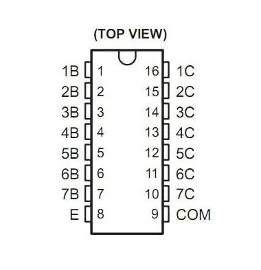
•Pin 1:CPU pulse input terminal, the port corresponds to a signal output terminal.
•Pin 2:CPU pulse input terminal.
•Pin 3:CPU pulse input.
•Pin 4:CPU pulse input.
•Pin 5:CPU pulse input.
•Pin 6:CPU pulse input terminal.
•Pin 7:CPU pulse input terminal.
•Pin 8:Ground.
•Pin 9:This pin is the common terminal of the cathode of the seven internal freewheeling diodes. The anode of each diode is connected to the collector of each Darlington tube. When used for inductive loads, this pin is connected to the positive pole of the load power supply to achieve freewheeling. If this pin is connected to ground, it is actually the collector of the Darlington tube that is connected to ground.
•Pin 10:Pulse signal output terminal, corresponding to pin 7 signal input terminal.
•Pin 11:Pulse signal output terminal, corresponding to pin 6 signal input terminal.
•Pin 12:Pulse signal output terminal, corresponding to pin 5 signal input terminal.
•Pin 13:Pulse signal output terminal, corresponding to pin 4 signal input terminal.
•Pin 14:Pulse signal output terminal, corresponding to pin 3 signal input terminal.
•Pin 15:Pulse signal output terminal, corresponding to pin 2 signal input terminal.
•Pin 16:Pulse signal output terminal, corresponding to pin 1 signal input terminal.
IV.Features of ULN2003
•Integration: ULN2003 is an integrated circuit, which consists of seven independent switch (transistor) channels, each channel can independently control an external load. Therefore, it can control multiple external devices on a single chip.
•High current drive: ULN2003 can provide current output up to 500mA per channel, which makes it very suitable for driving most small motors and some medium-sized motors. This high current driving capability makes ULN2003 widely used in many electronic systems, especially in those systems that require high efficiency, high precision, and high reliability control. For example, ULN2003 is a very commonly used chip in fields such as robots, printers, server motors, and industrial control.
•High voltage capability: ULN2003 is capable of withstanding higher voltages, typically operating in the 5V to 50V range. This makes it suitable for the control of various motors and inductive loads.
•Input voltage compatibility: The input terminal of ULN2003 is compatible with logic gate levels, usually within the 5V range, so it can be easily integrated with digital circuits.
•Impedance matching: The output of the ULN2003 has a high impedance, which allows it to effectively drive inductive loads such as stepper motors.
•Free-Drip Diode: Each channel includes a free-drip diode to protect against back EMF generated when switching.
•Low input power consumption: The input terminal of ULN2003 has low power consumption, which helps to reduce the energy consumption of the system.
•Stability: ULN2003 generally has good stability and reliability and is suitable for a variety of applications, including automation, robotics, printers, relay control, etc.
•High safety: ULN2003 stepper motor driver has high safety, is not prone to failure during use and has a long service life.
•External power supply: ULN2003 stepper motor driver usually requires an external power supply, and different voltages can be selected as needed to achieve greater torque control.
•Strong driving capability: ULN2003 stepper motor driver has high current output capability and can effectively drive high-power stepper motors.
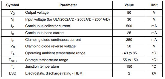
Ⅴ.Absolute maximum ratings of ULN2003
Frequently Asked Questions
1.What is the use of ULN2003?
The ULN2003 stepper motor driver module is used to drive stepper motors, high current LEDs and relay modules. This IC utilizes Darlington pairs to drive the output and can deliver up to 5V and 500mA. The power required to drive the transistor is taken from the control input, so there is no Vcc pin on the IC.
2.What is the maximum input current of ULN2003?
The ULN2001, ULN2002, ULN2003 and ULN2004 are high-voltage, high-current Darlington arrays, each containing seven open-collector Darlington pairs with a common emitter. Each channel is rated at 500 mA and can withstand peak currents of 600 mA.
3.How many input pins does ULN2003 have?
ULN2003 is a 16-pin IC. It has seven Darlington pairs inside, each of which can drive loads up to 50V and 500mA.
4.What is the difference between ULN2003 and ULN2003A?
ULN2003 and ULN2003A are two similar integrated circuits, but they have some subtle differences. The main difference lies in the voltage rating and the specific values of some parameters. The voltage rating of ULN2003 is typically 50V, while the voltage rating of ULN2003A is typically 20V.