Camshaft Position Sensor technology analysis

By Camshaft Position Sensor 2650

Camshaft Position Sensor technology analysis

The “Baton” of Engine Control – Basic Principle Explained

Where Is the Sensor Hidden?

Warning Signs: 5 Main Symptoms of Sensor Failure

Fault Check: Four-Step Inspection Guide

Repair Guide: Key Steps to Replace the Sensor

Sensor Showdown: Which Type Is Best?

Key Uses: The Brain of Smart Engines

Pro Testing: 3 Test Methods

Frequently Asked Questions


The “Baton” of Engine Control – Basic Principle Explained


Core Function: The Engine’s “Phase Eye”


Like a precise map in the commander’s hand, the CMP sensor (Camshaft Position Sensor) detects the camshaft’s exact angle and position in real time.

It quickly sends the camshaft’s position, the engine’s working cycle (intake/compression/power/exhaust), and the top dead center of cylinder No. 1 to the engine brain (ECU, Engine Control Unit).

Core purpose: The ECU uses this to control the fuel injection order and ignition timing. This ensures smooth and efficient engine running. Wrong injection? Late ignition? This sensor helps prevent that!


Two Main Sensing Principles


Magnetic Induction Type (VR Sensor) – Classic and Reliable:

Main parts: permanent magnet + coil + toothed target wheel.

Working principle: When the gear rotates, it changes the magnetic field. This causes the coil to create AC voltage (alternating current) like a pulse.

Signal feature: The voltage changes a lot. Higher speed means stronger and faster pulses. ECU must process the zero-crossing points carefully.


Hall Effect Type (Mainstream Choice) – Fast as Lightning:

Main parts: permanent magnet + Hall chip + notched metal plate or magnetic target wheel.

Working principle: Changes in magnetic field cause the chip to send a digital switch signal (square wave).

Signal feature: The signal is very stable. It switches clearly between high and low voltage. It works well at low and high speeds. Modern ECUs process it better and resist interference more strongly!


CMP vs CKP: Two Must-Have Partners in Engines


Strong relationship:

The CKP (Crankshaft Position Sensor) tells crankshaft speed and angle. But it cannot know cylinder status. The CMP tells camshaft phase. Together, they achieve accurate control.

The ECU uses both signals to manage injection and ignition. It also supports variable valve systems. Both are essential!


Main task difference:

CMP watches the camshaft. It handles valve timing and cylinder identification (which cylinder to fire).

CKP watches the crankshaft. It controls engine speed and stroke angle.


Different positions: CMP is usually on the cylinder head or near the camshaft end.

Different failures:

If CMP fails: hard to start, high fuel use.

If CKP fails: engine won’t run at all!


Where Is the Sensor Hidden?


Easy to locate:

  • Most are on the valve cover or cylinder head top. They watch the camshaft closely.
  • They sit near the camshaft sprocket or timing gear for exact alignment with the target wheel.
  • In high-end cars, the sensor is inside the camshaft end cap to save space.
  • Some are built into the cylinder head for a compact design.


How to recognize it?

  • It looks like a small cylinder or box, with 2 or 3 wires (2 for magnetic, 3 for Hall).
  • It is near the camshaft, points to the target wheel, and has a visible wiring connector.


Warning Signs: 5 Main Symptoms of Sensor Failure


What drivers may notice:

  • Hard to start, especially when hot
  • Rough and shaky idling
  • Weak acceleration
  • Sudden increase in fuel use
  • Yellow “Check Engine” light comes on


Hidden system risks:

  • ECU activates limp mode (limits speed to 60 km/h)
  • Variable valve timing stops working, hurts performance and fuel economy
  • DTC (Diagnostic Trouble Code) like P0340/341/342 appears


Fault Check: Four-Step Inspection Guide


  • Read the DTC code: Plug in an OBD scanner.
  • Check with eyes: Look for broken, dirty, corroded, or loose connectors. Make sure the target wheel is clean.
  • Check the power circuit: Inspect the fuse and relay.
  • Deep signal test: Use a voltmeter or oscilloscope to measure voltage or waveform.


Repair Guide: Key Steps to Replace the Sensor


Before starting: Make sure the sensor itself is bad, not the wiring or target wheel.


Ten standard steps:


  1. Use an original or matching sensor (same model and type!).
  2. Disconnect the battery negative terminal (safety first!).
  3. Unplug the connector.
  4. Remove the screw or clip.
  5. Gently take out the old sensor (don’t scratch the hole or target wheel).
  6. Clean the seat (remove oil and glue).
  7. Install the new one carefully (tighten the bolt with correct torque).
  8. Plug in the connector (listen for the click!).
  9. Reconnect the battery.Final calibration: Clear the code and start the engine. Is idle smooth? Acceleration okay? Light off? Then it’s a success!


Sensor Showdown: Which Type Is Best?

Sensor Type Signal Output Type Zero-Speed Detection Signal Stability Oil Resistance
Magnetic Induction Type Analog AC waveform (alternating current waveform) No Weak signal at low speed Medium
Hall Type Digital square wave (square-shaped digital signal) Yes Stable at all speeds Very good (four and a half stars)
Optical Type Precise pulse signal (accurate light-based pulses) Yes Excellent (five stars) Easily affected by oil


Key Uses: The Brain of Smart Engines


Core for precise timing control:

  • Sequential fuel injection: Each injector opens right during the intake stroke.
  • Millisecond ignition trigger: Spark plug fires at the best time.
  • VVT/VANOS (Variable Valve Timing): The system adjusts valve timing using camshaft position.


Needed for new technologies:

  • Start-stop system: Quickly finds camshaft position for smooth restart.
  • Hybrid cars: Helps switch between motor and engine smoothly.
  • Emission rules: Reliable signals help meet OBD standards.


Pro Testing: 3 Test Methods


Prepare these tools:

  • Digital multimeter
  • Automotive oscilloscope (recommended)
  • Repair manual (to check pinouts)

         Safety first: Turn off power and unplug battery!


Static Test (for Hall type):

  • Check voltage at power pin (key ON): usually 5V or 12V
  • Check ground pin resistance: should be around 0Ω
  • For magnetic type, measure coil resistance (follow manual)


Dynamic Signal Capture (Best Way!)

  • Back-probe method:
  1. Plug in the connector
  2. Insert scope/meter probe into signal wire
  3. Start the engine and capture the waveform
  • Hall type waveform: Clean square wave (0V↔5V), frequency increases with RPM ANTAIANLONG new Hall chip responds 50% faster. Edges are sharp like blades. ECU reads faster!
  • Magnetic type waveform: Sine wave. Idle voltage ≈0.5V. Gets stronger when engine revs.


Target Wheel Check (engine off):

  • Any missing teeth? Bent? Dirty? Replace it!
  • Measure air gap (common value: 0.5–1.5mm)
  • Try moving the wheel by hand—must not move!


Diagnostic Rule:


Signal lost / voltage wrong / bad waveform → Replace sensor!

Also check wiring and ECU: Look for broken wires and wrong reference voltage.

Only combine DTC + symptoms + test data for a full answer!


Frequently Asked Questions


What does a camshaft position sensor do?

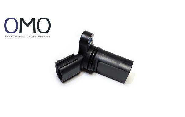
The Camshaft Position Sensor (CMP), an electronic device within an internal combustion engine, ​​determines​​ both the speed (RPM) and position of the camshaft. This data is ​​essential​​ for the Engine Control Unit (ECU) to ​​precisely manage​​ various engine ​​functions​​.


How does a camshaft sensor work?

Based on the Hall effect principle, the camshaft sensor detects the movement of the camshaft's gear ring. This rotation alters the Hall voltage within the sensor's Hall IC, and the resulting change is sent to the ECU as a digital signal.


Where is the camshaft position sensor?

The camshaft position sensor is typically found in the engine's cylinder head. Its cylindrical body extends into the head, enabling precise monitoring of the camshaft's rotation and position.


What causes camshaft sensor to go bad?​

Camshaft position sensor failure can be caused by factors like damage to the sensor itself, electrical issues, contamination from oil or debris, environmental conditions, improper installation, or failures within the ECU/system.

Kategorien

Top