By Magnetic Sensor vs Hall Effect Sensor 4018
Core Concepts and Technical Basics
In-Depth Comparison of Key Differences
Solutions for Design Challenges
A magnetic sensor is a device that detects changes in magnetic field strength or direction. Its main job is to convert invisible magnetic signals into measurable electrical signals. In industrial automation and consumer electronics, it acts like a "magnetic sense nerve" for the device, sensing the magnetic environment in real time.
The sensor mainly works based on physical effects like magnetoresistance effect and electromagnetic induction. When a magnetic field acts on sensitive materials, it causes clear changes in resistance or voltage.
| Type | Working Principle | Sensitivity/Accuracy | Power Usage |
| AMR Sensor | Anisotropic Magnetoresistance | Medium (≈1 percent) | Medium |
| TMR Sensor | Tunnel Magnetoresistance | Very High (up to 0.1 percent) | Microamp level |
| Hall Switch | Hall Effect | Low | Milliamp level |
| Fluxgate | Magnetic Saturation Effect | Very High (ppm level) | High |
Note: TMR sensors stand out for high sensitivity and ultra-low power use. They are ideal for energy-efficient systems.
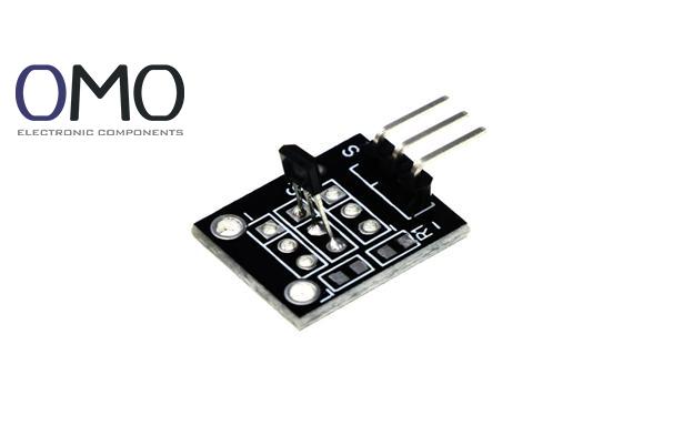
The Hall sensor is an important sub-type of magnetic sensors. It is based on the Hall effect, discovered in 1879. When current (I) flows through a conductor perpendicular to a magnetic field (B), the moving charges feel a Lorentz force and create a sideways voltage (U<sub>H</sub> = K<sub>H</sub> × I × B).
With semiconductor progress, Hall sensors moved from labs to mass production. There are three main types:
The two sensors differ in energy needs and response methods. Hall sensors need external power (1-10mA), and they work by using Lorentz force to deflect charge carriers.
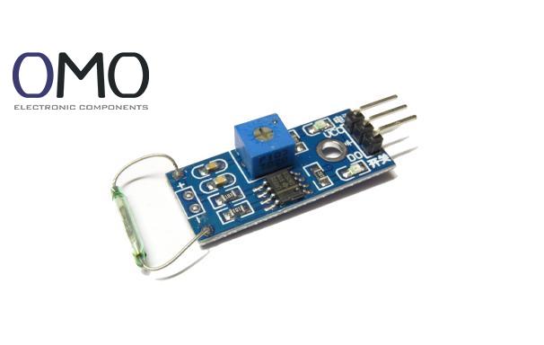
In contrast, magnetic sensors include other methods like AMR, which relies on resistance change in ferromagnetic materials. Some types like Reed Switch can even work with zero power when idle. This makes a big difference in battery-powered IoT devices, where power saving is key.
Linear Hall points gather in the lower left (10-50mV/mT, >1mA), AMR is in the middle (50-80mV/mT, 100μA),
TMR reaches the top right (>100mV/mT, <10μA), showing a large performance gap.
Hall sensors (red line) show wide swings from -40°C to 125°C, with ±5 percent error.
TMR (blue line) stays smooth in the same range, with only ±0.5 percent drift, perfect for high-precision systems.
Hall sensors have a bandwidth under 100kHz. When signal frequency goes higher, output drops fast.
GMR and TMR stay stable even at MHz levels.
Temperature stability is vital for car motor control systems.
One electric vehicle brand found that at 125°C in the engine, regular Hall sensors caused 3.2mm position error, while TMR sensors cut this to just 0.15mm, meeting ASIL-D safety standards.
In small wearables, Hall chips must be smaller than 0.5mm² to avoid signal loss.
GMR/TMR, using thin-film tech, can reach the same performance in just 0.1mm².
In consumer electronics, Hall switches dominate flip-cover detection because of low cost (under 0.1 USD) and simple design.
In smartphones, a single Hall chip plus a tiny magnet enables wake-up in microseconds, adding less than 0.5 RMB to the total cost.
In cars, seatbelt detection uses Hall switches too, with IP67 protection and over 100000 mechanical cycles, meeting automotive standards.
In EV charging modules, 100A current test shows traditional Hall (purple line) had ±1.5 percent error,
but TMR (gold line) stayed within ±0.25 percent. This improves range estimation and battery health.
In oil drilling panels, the magnetic system faces 150°C heat and heavy vibration.
Fluxgate sensors, using magnetic saturation, kept 0.5° heading accuracy even in 175°C / 100MPa, cutting drilling error to 0.01 percent.
| Scene Type | Key Requirements | Hall Solution | Special Magnetic Solution |
| Motor Commutation | Low cost, medium accuracy | ⭐⭐⭐⭐ | ⭐⭐ |
| Large Current Sensing | μT-level resolution | ⭐ | ⭐⭐⭐⭐ (TMR) |
| Geological Equipment | nT-level weak field | ✘ | ⭐⭐⭐⭐ (Fluxgate) |
Hall sensors use built-in smart correction circuits.
For example, Allegro ACS72x has a low-pass filter that reduces PWM noise by 40dB in BLDC motors.
Also, improved common-mode rejection in GMR bridges helps robot torque sensors reach 90dB signal-to-noise ratio.
Three Anti-Interference Techniques:
Mechanical stress affects magnetic sensors badly.
One encoder case showed an AMR chip without cover shifted 5mT from stress.
After adding stress buffer layers, drift dropped to 0.3mT.
New Hall latches use hysteresis control to keep zero false triggers even in 20G vibration.
Combining CMOS tech with magnetic sensors is changing the game:
TMR modules with Wake-on-Magnet (like TDK TMR58xx) cut standby power to 70nA, helping Bluetooth trackers last longer.
Stacking GMR thin films with signal ASICs reduces size by 80 percent (only 3×3mm) and boosts power density by 300 percent.
Smart Hall sensors like Infineon XENSIV™ combine 32-bit MCU for magnetic sensing, logic control, and output—all in one chip.
The operation of magnetic sensors relies on measuring alterations in the magnetic moment of a material within a magnetic field. Exposure to a changing magnetic field generates a voltage proportional to the field intensity.
A magnetic sensor is an instrument designed to identify alterations in a magnetic field and translate them into a quantifiable electrical output.
Operating on the Hall Effect principle, a Hall Effect sensor is a magnetic field detector that identifies a field's existence, intensity, and directional polarity.
A Hall effect sensor can be tested by attaching a voltmeter to its output terminal. Ensure the voltage output meets expectations when exposed to a magnetic field. Failure to do so indicates a potential sensor defect.