Thermal Cutoff (TCO) Explained: Working Principle, Applications, and Maintenance Guide

By Thermal Fuse 2768

Thermal Cutoff (TCO) Explained: Working Principle, Applications, and Maintenance Guide

Basic Concept and Principle

Technical Parameters and Features

Common Applications

Testing Method for TCO

Test Steps

How to Replace a TCO

Common Failure Causes and Modes

Frequently Asked Questions


Basic Concept and Principle


Definition


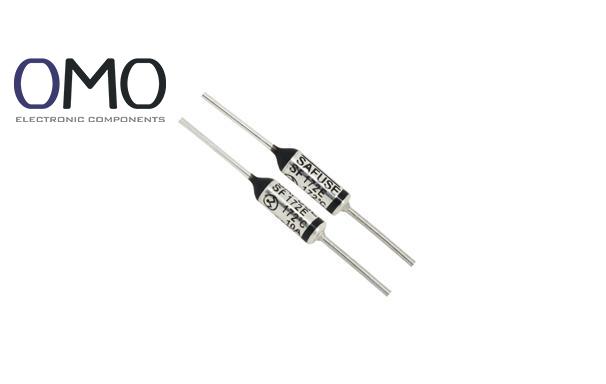
A Thermal Cutoff (TCO) is a precise one-time temperature-sensitive protection component. It acts as the "last line of defense" for device safety. When the temperature goes over a set limit, it cuts off the circuit exactly. Unlike a current fuse, a TCO is made to react to temperature problems. Its main job is to stop fires or permanent damage caused by overheating.


Key Differences from a Normal Fuse


  • Trigger mechanism: TCO responds to temperature, while a normal fuse responds to too much current (overcurrent).
  • Reset type: TCO is non-resettable (once it breaks, it stays open), but many fuses are resettable (like PPTC).
  • Response speed: TCO speed depends on heat transfer rate, while fuse speed depends on I²t value (current squared times time).


Comparison Table: TCO vs Normal Fuse

Feature Thermal Cutoff (TCO) Normal Fuse
Trigger Factor Temperature Overcurrent
Reset Type Non-resettable Resettable/Not
Main Protection Target Overheating Overcurrent/Short
Speed Factor Heat transfer rate I²t value


Detailed Working Principle


The key part of a TCO is a heat-sensitive material (like BiSn/PbSn alloy or organic compound). When the temperature reaches a set point (for example, 142°C ±5°C), the material melts (solid-liquid phase change). A spring or piston inside then pushes the contact apart. This action breaks the circuit forever. This is why it is a one-time protection device and helps stop further damage.


Key Role and Application Value


The main goal of a TCO is to break the chain of overheating. It protects parts like hairdryer heaters, motor windings, and lithium battery packs. This helps avoid fires (follows UL 1434, IEC 60691 standards). Safety groups like UL, TUV, and CCC require TCOs in certain devices. It is a must-have for safety approval.


Technical Parameters and Features


Key Performance Indicators


When choosing a TCO, focus on these four things:

  • Rated Temperature (RT): Set action point (e.g. 100°C) and tolerance (e.g. ±5°C). Smaller tolerance = higher precision.
  • Electrical Capacity: Max current (e.g. 10A) and voltage (e.g. 250V). It must handle the device’s load.
  • Trigger Curve: As temperature goes up, reaction time goes down. Match the time vs temperature curve with your device.
  • Mechanical Strength: Can resist vibration (e.g. 10G@55Hz) and shock (e.g. 100G@6ms). Important for car systems.


Package Type and Installation


  • Lead Type: Axial (straight legs) fits through-hole welding; Radial (bent legs) saves space.
  • SMD Type: Best for auto machines and small devices like phone charging ICs.
  • Insulation Level: UL94 V-0 is flame-resistant and safe at high temps. Solder pins below 260°C for under 3 seconds, or use crimping.


Common Applications


Home Appliances


  • Hairdryers use a TCO to cut power in 3 seconds during overheating. This stops the plastic case from melting.
  • Coffee machines use a 72°C TCO on the heating plate to stop dry heating over 300°C.
  • Washing machine motors use a 130°C TCO inside the winding. This cuts motor failure by 80%.


Electronics and Power Devices


  • Switch-mode power supplies use a 132°C TCO after the transformer as backup (PTC can overheat again).
  • Lithium battery packs add a 149°C TCO next to the BMS. This gives double protection and no leakage current.
  • IGBT heat sinks use a 90°C TCO. It reacts 200ms faster than normal thermal switches to stop avalanche breakdown.


Industry and Special Use


  • Electric drills use a 105°C TCO on the shell. It resists vibration better than a bimetal switch.
  • Car seat warmers use a 77°C TCO that works in 95% humidity.
  • PV (solar) inverters use SMD TCOs on heat sinks that last over 10 years in -40°C to 150°C cycles.


Testing Method for TCO


Required Tools


  • Digital multimeter (Continuity/Ohm mode)
  • Programmable heating platform (±1°C precision)
  • High-temp tweezers (ceramic/PTFE coating)
  • IR thermometer (0–250°C)
  • Insulation tester (500VDC)
  • Safety gear: goggles + heatproof gloves


Test Steps


Offline Test


  • Power off and cool to room temperature (wait as long as manual says).
  • Visual check: No cracks/burns/rusty pins.
  • Continuity test: Resistance should be <0.5Ω. If open, it failed.
  • Strange readings: >1Ω or open = replace it.


Simulated Condition Test


  • Heat up slowly at 3°C/min to RT–15°C (e.g. for 100°C rating, heat to 85°C).
  • Hold 30 minutes. TCO must stay closed (working).
  • Keep heating to RT+5°C (e.g. 105°C). Time to open must match response curve (usually <2 minutes).


How to Replace a TCO


Before Replacing


  • Safety First: Power off and discharge capacitors (voltage <36V).
  • Pick the right part:
  1. Match temperature rating (±5°C)
  2. Current ≥150% of old TCO (e.g. old = 10A → pick 15A)
  3. Right size and pin type
  • Make sure there is at least 5x5mm for soldering.


Step-by-Step Process


  • Cut old TCO pin (5mm from body), clean pads with desolder pump.
  • Use sandpaper to polish pads until shiny.
  • Pre-shape new pins (don’t bend near body). Follow pin polarity if marked.
  • Solder below 350°C, under 3 seconds. Use solder wire with 2% silver.
  • Put 3mm heat-shrink tube over pins. Shrink with hot air (120°C).


After Replacement Check


  • Continuity test: Resistance <0.5Ω (use 200Ω range).
  • Insulation test: Pin-to-pin resistance >100MΩ (500VDC tester).
  • Load test: Case temperature must stay ≤45°C (check with IR gun).
  • Function test: Use hot air to trigger overheat. Use multimeter to confirm circuit is open.


Common Failure Causes and Modes


Early Trigger (False Action)


  • Poor cooling: Thermal grease dried or airflow blocked (heat resistance ↑30%).
  • Bad placement: TCO above hot part (rising heat gives wrong signal).
  • Power spikes: Switching power spikes cause fast heating. Add RC snubber to fix it.


No Protection (Fails to Trigger)


  • Wrong type: 155°C TCO used for 100°C job.
  • Bad contact: Gap >0.1mm between TCO and part. Fill it with thermal pad.
  • Mechanical jam: Spring gets stuck after many uses, especially with vibration. Failure chance ↑23% after 1000 heat cycles (lab report).


Physical Damage


  • Pin stress: Bend radius <2x pin size → causes break inside.
  • Corrosion: Sulfur in the air damages electrodes (47% higher fail rate near the sea).
  • Solder damage: Iron contact >5 seconds changes sensor material (action temp shifts ≥10%).
  • External hit: Drop >50G bends the structure.


Frequently Asked Questions


Where is the thermal fuse on a dryer?​

For both electric and gas dryers, the thermal fuse is typically situated behind the rear panel or at the machine's bottom. Behind the rear panel, it's commonly found along the exhaust duct near the heating element or blower.


What is a thermal fuse?​

A thermal fuse acts as a safety device, automatically interrupting electrical power to appliances like dryers if they overheat. This shutdown prevents potential damage and lowers the fire risk.


What does a thermal fuse do?

A thermal fuse serves as a safety device. It interrupts power to the heating element if an appliance malfunctions or stops working unexpectedly, thereby preventing dangerously high temperatures.


What does a fan thermal fuse do?

A thermal fuse cuts off power to prevent the fan from overheating, reducing fire or equipment damage risk. If your fan suddenly stops, a tripped thermal fuse could be the cause.

Kategorien

Top