By Wire Wound Resistor 3091
What is a Wire Wound Resistor?
Working Principle: From Physics to Thermal Balance
Main Features: Strong Electrical and Physical Performance
Applications: Cross-Industry Solutions
Usage and Selection Guide: Key to System Reliability
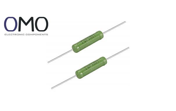
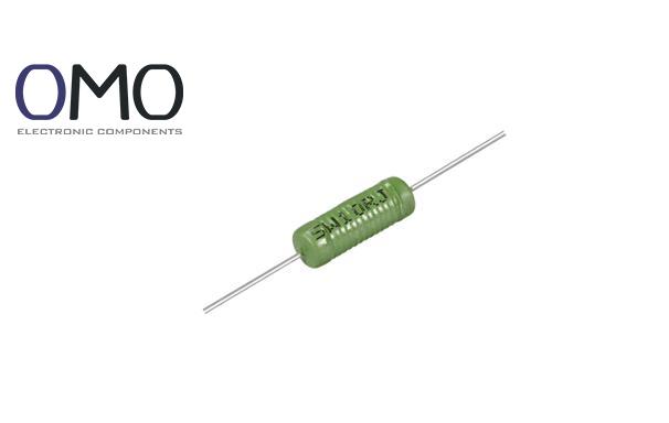
A wire wound resistor is an electronic component made by winding a helical alloy wire around an insulated base. Unlike traditional carbon film or metal film resistors, it uses high-purity alloy wire (such as nickel-chromium or copper-nickel alloy) as the main resistive material, not a thin film coating. This gives it clear advantages: carbon film resistors are easily affected by temperature drift and have weak power capacity, while wire wound resistors use solid alloy wires for better stability and can handle high power loads over 1000W.
The core structure uses a modular design. A ceramic insulation base gives mechanical support. The spiral-shaped resistive alloy wire wraps around the base to form the resistance path. An insulating cover (like enamel or silicone) protects the surface from corrosion. Metal end caps allow connection to circuits. As shown in the diagram, the current flows clearly—when electrons pass through the alloy wire, they lose energy through collisions, turning electrical energy into heat. Compared to flat-film resistors, this spiral design greatly improves heat dissipation.
Wire wound resistors have strong advantages in industry:
| Type | Structural Feature | Common Use |
| Power Type | Open winding | Dummy loads in power devices, motor braking |
| Precision Type | Sealed ceramic tube | Standard resistors in multimeters, medical devices |
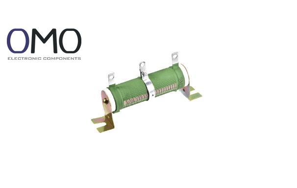
| Adjustable Type | Sliding contact design | Circuit calibration, lab adjustment |
| Non-inductive Type | Dual winding, reverse pattern | High-frequency inverters, radar systems |
When current flows through the spiral alloy wire, electrons hit the atomic lattice, producing resistance as per Ohm’s Law (V = IR). As shown, heat is created by Joule’s Law (P = I²R), where over 90% of electrical energy turns into heat. The heat then flows out step by step—from the ceramic base to the cover to the surrounding air. In the temperature-resistance curve, a 50°C rise causes only 0.01% resistance change, which is far better than the 0.5% drift in film resistors.
Wire wound resistors use a thermal balance design. The alloy wire spreads heat evenly to avoid hot spots. In power-type resistors with open windings and forced air cooling, the temperature rise stays under 30°C. In contrast, oxide film resistors rise over 50°C under the same conditions. This is thanks to good thermal conductivity of packaging materials—for example, ceramic bases reach 1.5W/m·K, which helps release heat quickly.
Though the parasitic inductance limits high-frequency use (above 10kHz needs non-inductive types), the benefits often outweigh the cost (about 20% higher than thick film types). In pulsed loads—like discharge circuits in photovoltaic inverters—its current endurance is 50% better, avoiding burn-out problems. Large size (e.g., a 100W model is ~50mm long) can be offset by using heat sinks.
Wire wound resistors give reference resistance in multimeter circuits, with less than 0.05% yearly drift—much better than carbon film’s 0.5%. Medical sensor circuits use their low TCR to keep ECG monitoring accurate. For example, in bridge measurement circuits, the error is under ±0.01%.
Selection follows a clear logic: calculate derating for actual power needs (e.g., at 40°C ambient, use rated power × 0.8). As the flowchart shows, if working frequency >10kHz, choose non-inductive type; otherwise, use the standard type. For high-speed switching in industrial inverters, this is essential.
Regular resistance drift checks are important (±1% threshold per year). Use fuses in series for overload protection. Comparison:
Wirewound resistors offer inherent advantages, including high precision, low temperature coefficient, excellent heat resistance, and the ability to operate normally at ambient temperatures up to 170°C.
Wirewound resistors are formed by winding resistive wire (such as nickel-chromium, manganese-copper, or constantan) onto an insulating core or frame.
Wirewound resistors, essential in various industries, are chosen for applications demanding high power handling, precision, stability, and low noise.
Wirewound resistors operate by dissipating electrical energy as heat via a resistive wire element. This construction provides high power handling capability and dependable performance across a broad spectrum of applications.